ENGINEERING PROJECT
5-Inch FPV Drone Build
5-Inch FPV Drone Build
FPV Drone Assembly, Configuration, Testing, and Troubleshooting.
FPV Drone Assembly, Configuration, Testing, and Troubleshooting.
This project involved building, configuring, and testing a 5-inch FPV drone system. The work included electrical assembly, soldering, flight controller setup, radio receiver configuration, video system integration, battery setup, antenna mounting, troubleshooting, and safety testing. The original goal was to build a lightweight, acrobatic freestyle drone capable of aggressive maneuvers, and the finished build met that goal, while giving me hands-on experience with real-world electronics, embedded systems, and mechanical integration.
6S LiPo Power
Betaflight
ELRS + DJI O4 Pro
Project Media
Project Media
Project Media
A clean set of replaceable placeholders for drone photos, wiring close-ups, testing footage, and configuration screenshots.

Completed FPV drone build

Flight controller and ESC wiring
Motor feet designed in Fusion 360
VTX antenna housing designed in Fusion 360
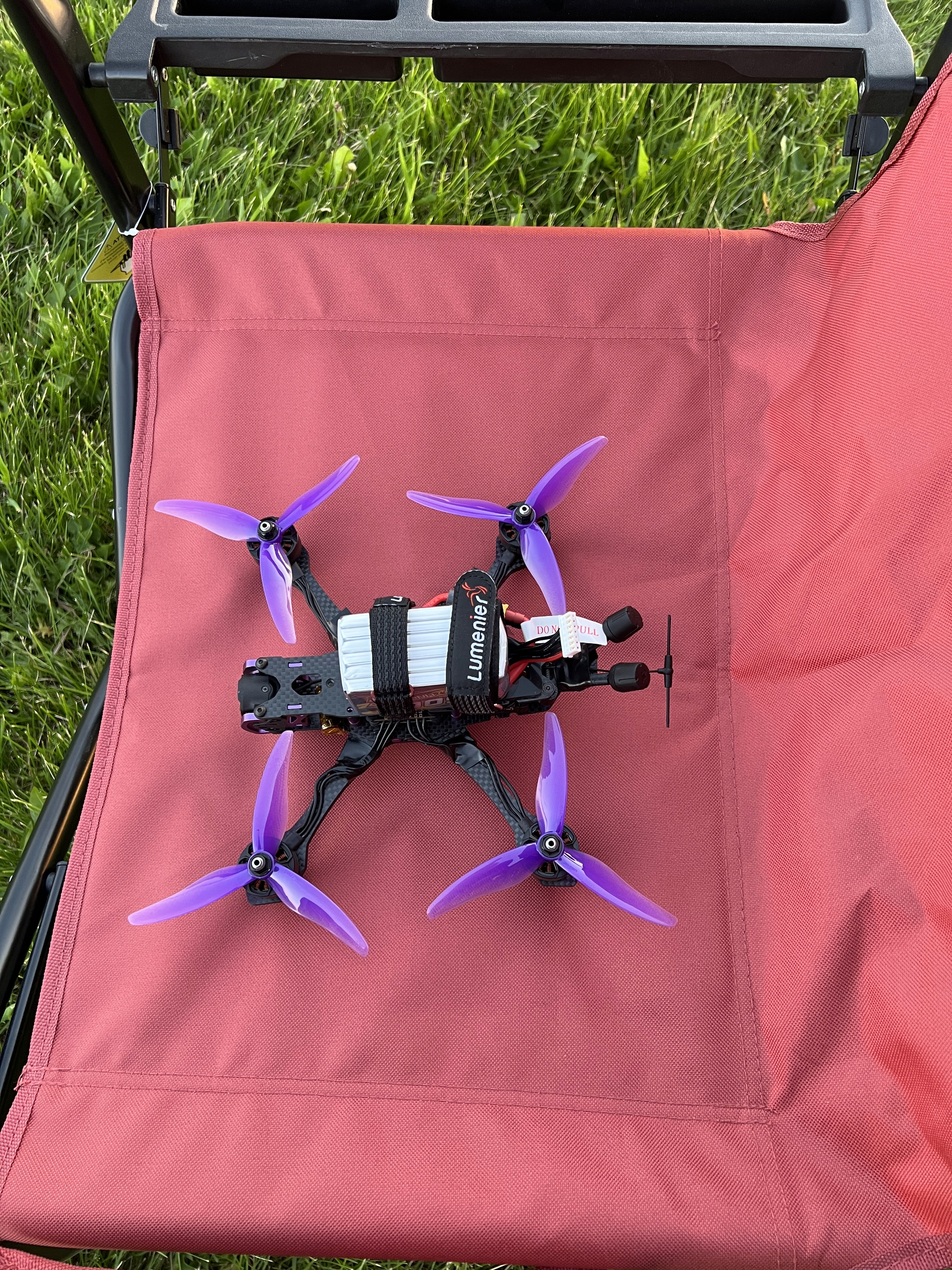
First Flight with the battery attached

VTX and receiver mounted + intial Betaflight setup and troubleshooting
Initial testing and configuration
Drone in flight
Research & Component Selection
Research & Component Selection
Before any soldering happened, I spent time understanding how each subsystem of an FPV drone actually works and how the parts need to fit together electrically and mechanically. Flight controllers, ESCs, motors, props, batteries, receivers, and video systems all have to be matched on voltage, current, size, and protocol. Pick the wrong combination and the drone either won’t fly or won’t survive its first hard landing. That research shaped every purchasing decision that followed.
Flight Controller & ESC Compatibility
Compared flight controller firmware targets, ESC current ratings, and communication protocols (DShot, bidirectional telemetry) to make sure the FC and 4-in-1 ESC could talk to each other reliably before buying either part.
Motor, Prop, and Battery Matching
Cross-referenced motor KV rating against propeller size and battery cell count (6S) to keep RPM, current draw, and thrust in a safe, efficient range for aggressive acro flying without overheating the motors or ESC.
Frame & Component Fit
Checked stack mounting-hole patterns (30.5mm / 20x20mm), arm thickness, and camera mount geometry against every electronic component before ordering, so nothing would show up too large, too heavy, or physically incompatible with the frame.
Radio & Video Link Research
Researched ExpressLRS against other radio protocols and DJI’s O4 digital video system, comparing range, latency, and weight to settle on a link that would stay reliable at acro flying speeds and distances.
Sourcing & Budget
Read build logs, forum threads, and reviews to validate part choices against my budget before purchasing, prioritizing components with strong community support so troubleshooting problems later would be easier.
Build Process
Build Process
01
Planning and Component Layout
Before touching a soldering iron, I mapped out where every component needed to sit inside the 5-inch frame: flight controller stack, ESC, receiver, O4 Pro air unit, capacitor, and battery straps. I worked on wire length and keeping high-current paths short, isolating the receiver antenna from noisy power wires, and leaving clearance for the props. Getting this layout right up front saved a lot of rework later.
02
Frame Assembly
Assembled the 5-inch carbon fiber frame arm by arm, torquing standoffs evenly so the frame stayed square under crash loads. I test-fit the flight stack, camera, and antenna mounts before final tightening to confirm nothing would need to be unbolted later, then set aside dedicated mounting points for the battery strap and battery leads
03
Electrical Soldering
Mounted the 4-in-1 ESC and soldered the motor phase wires, XT60 battery leads, capacitor. Each joint had to be clean, shiny, and mechanically sound. A cold joint or bridged pad this close to a LiPo battery can mean a fire, not just a bad connection. After every few joints I checked continuity with a multimeter and inspected under magnification before moving on. I also designed and 3d printed motor feet to help dampen crashes around the motor bell housing.
04
Flight Controller Setup
Mounted the flight controller on its own soft-mount grommets to isolate it from frame vibration, then wired it to the ESC over the shared communication bus. Flashed the latest Betaflight firmware, set the correct board orientation, calibrated the accelerometer, and set default PID and filter settings so the aircraft would hold attitude cleanly during initial testing to dial in the PIDS and filters
05
Radio Link Setup
Installed the ExpressLRS receiver on top of the O4 Pro air unit, soldered its signal and power leads to the flight controller, and bound it to the transmitter. I mapped every channel, verified stick and switch response in Betaflight’s receiver tab, and configured a dedicated arming switch with failsafe behavior set to disarm, a critical safety step before any motor testing.
06
Video System Setup
Installed the DJI O4 Pro Air Unit on the rear of the frame, then designed and 3D-printed a flexible TPU antenna mount to keep the video antennas clear of the props and carbon frame, both of which can block or reflect signal. I angled the antennas for consistent coverage and confirmed a clean digital feed on the goggles before moving on to safety checks.
07
Safety Checks
Before the first full-power connection, I ran the whole electrical system through a smoke stopper to catch any short circuit safely, rechecked continuity across every solder joint, verified polarity on the battery leads, and confirmed the props were off. Only after everything checked out clean did I move to powered testing.
08
Motor and Flight Testing
With props still off, I verified motor direction and throttle response for all four motors in Betaflight’s motor test tab, I then moved to careful a hover test to make sure prop direction and motor direction matched and that all systems were working correctly. I then gradually worked up to full-throttle acrobatic maneuvers to confirm the build could handle the flight style it was designed for.
Engineering Challenges
Engineering Challenges
A 5-inch quad packs a flight controller, ESC, receiver, video system, capacitor, and battery leads into a frame with barely any spare room. Nearly every difficulty in this build traced back to that constraint: components had to be soldered cleanly in tight quarters, then packaged so nothing shorted, rubbed through its insulation, or blocked signal.
Solder Joint Quality
The hardest part of this build wasn’t planning. It was getting clean, reliable joints on high-current connections like the XT60 power lead and motor phase wires, working in a space barely bigger than the components themselves. A cold joint, a bridged pad, or a nick in the insulation this close to a LiPo battery can start a fire, so every joint got reworked, inspected under magnification, and continuity-tested before it was trusted.
The two joints below are examples of failures I caught while soldering and corrected before continuing the build process.

Negative capacitor wire not bonding over the negative lead

Positive XT60 lead not bonding cleanly to the power pad
Flight Controller Orientation
Identified and corrected flight controller orientation issues in Betaflight.
Receiver and Telemetry Setup
Tested ELRS receiver behavior, channel mapping, RSSI, and link quality.
Component Packaging
A 5-inch frame leaves very little room for the flight stack, receiver, capacitor, and battery straps once everything is wired in. Routing power and signal wires without them rubbing against carbon fiber edges, positioning antennas away from noisy power lines, and keeping the battery strap accessible all had to be solved inside a very small space
Safe Power Testing
Used a smoke stopper and staged testing process to reduce the risk of damaging electronics.

Carbon fiber vs. a 3D-printed frame
Blackbox gyro data shows a clear gap between the pilot input band and the ~200Hz motor/prop noise peak. Carbon fiber’s stiffness keeps that buffer wide enough for the filters to tell real input from vibration; a 3D-printed plastic frame flexes more and would have pulled that noise peak closer, eating into the buffer and making the flight controller harder to tune.
Skills Demonstrated
Skills Demonstrated
Hands-on engineering practice across electrical assembly, embedded configuration, radio/video systems, power safety, mechanical packaging, and diagnostics.
Electrical Assembly
Soldered and inspected power leads, motor wires, receiver connections, and other electrical components.
Electrical Assembly
Soldered and inspected power leads, motor wires, receiver connections, and other electrical components.
Flight Controller Configuration
Used Betaflight to configure flight controller settings, receiver inputs, arming modes, orientation, and motor behavior.
Flight Controller Configuration
Used Betaflight to configure flight controller settings, receiver inputs, arming modes, orientation, and motor behavior.
Radio and Telemetry Setup
Configured ELRS radio control and monitored link quality, RSSI, and receiver performance.
Radio and Telemetry Setup
Configured ELRS radio control and monitored link quality, RSSI, and receiver performance.
Video System Integration
Integrated a DJI O4 Pro FPV video system and configured the drone for digital FPV flight.
Video System Integration
Integrated a DJI O4 Pro FPV video system and configured the drone for digital FPV flight.
Battery and Power Safety
Worked with 6S LiPo batteries, XT60 connectors, smoke stopper testing, and safe power-up procedures.
Battery and Power Safety
Worked with 6S LiPo batteries, XT60 connectors, smoke stopper testing, and safe power-up procedures.
Mechanical Integration
Installed components into a compact drone frame while managing spacing, wire routing, antenna placement, and durability.
Mechanical Integration
Installed components into a compact drone frame while managing spacing, wire routing, antenna placement, and durability.
Troubleshooting
Diagnosed setup issues involving solder joints, motor direction, flight controller orientation, receiver setup, and video/radio performance.
Troubleshooting
Diagnosed setup issues involving solder joints, motor direction, flight controller orientation, receiver setup, and video/radio performance.
What I Learned
What I Learned
This project strengthened my understanding of real-world electronics integration. Unlike a purely theoretical circuit or software assignment, the drone required careful physical assembly, testing, troubleshooting, and configuration. I learned how important solder quality, wire routing, component placement, firmware setup, and safety checks are when building an electrical system that must operate reliably under vibration, current spikes, and real flight conditions.
Practical takeaways
How to safely power and test a LiPo-based electronics system
How to diagnose configuration and wiring problems
How to use Betaflight for flight controller setup
How radio control, telemetry, video transmission, and motor control work together
How mechanical design choices affect electrical reliability
How to approach troubleshooting step by step
Future Upgrades
Future Upgrades
The build already achieves its original goal: a lightweight, acrobatic freestyle drone that flies aggressively and reliably. The next upgrade I’m considering is adding a GPS module to unlock position hold and return-to-home (RTH): letting the flight controller lock the aircraft’s position in a hover, and automatically fly it back and land if the radio link is ever lost. It’s a meaningful step beyond a purely acro-tuned setup, and would mean weighing the added weight and wiring against the drone’s freestyle handling.
Why This Project Matters
Why This Project Matters
This project demonstrates practical engineering ability beyond classroom theory. It required hands-on electrical assembly, system-level thinking, software configuration, safety awareness, and troubleshooting. The drone combines power electronics, embedded control, radio communication, video transmission, mechanical packaging, and real-world testing into one integrated system.
Interested in my engineering projects?
View my other projects or contact me to learn more about my technical experience.