ANALOG CONTROL PROJECT
Closed-loop analog PI control that holds a brushed DC motor at commanded speed under changing load.
For this electronics design project I designed, simulated, and built an electronic speed controller for a small brushed DC motor. A Hall-effect sensor on the shaft acts as a tachometer, a frequency-to-voltage converter turns its pulses into a feedback voltage, and an op-amp PI controller drives a MOSFET output stage from a 15 V supply so the shaft speed tracks the setpoint. The finished loop held steady-state speed within the ±10% requirement and switched cleanly between 2000 and 2400 rpm.
PI Control
Op-Amp Design
LTspice Simulation
Oscilloscope Testing
Sensor Feedback

The control loop, end to end
Difference amplifier, PI controller, MOSFET driver, and a simulated motor + tachometer model in LTspice.
View figures & test data ↓

Simulation plots and oscilloscope captures from the report, spanning the first LTspice sweep to the measurements that verified the ±10% speed requirement.
LTspice schematic of the complete loop: difference amp, PI controller, MOSFET driver, and behavioral models for the motor and tachometer.

Simulated drive voltage snapping to the new operating point at a proportional gain of 56. Lowering the gain to 5 made settling visibly slower.
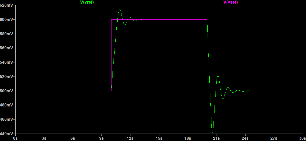
Vref locking onto Vset for 500 mV to 600 mV setpoint steps, confirming the loop model reaches steady state with matching voltages.

Bench measurement of Vref alternating between the 0.5 V and 0.6 V setpoints, the basis for the ±10% verification statistics.

Oscilloscope capture of the frequency-to-voltage converter output; a 67 Hz input measured 1.023 V, a 2.3% deviation from the design target.

Vref and Vset captured together while stepping the speed command, showing the feedback following each transition.
Verification against the project requirements: the steady-state difference between Vset and Vref stayed within ±10% at every tested operating point.
0.5 V SETPOINT
0.4926 V
Mean measured Vref of 0.4926 V with 97.6% of samples inside the ±10% band. Requirement met.
0.6 V SETPOINT
0.5920 V
Mean measured Vref of 0.5920 V with 97.9% of samples inside the ±10% band. Requirement met.
SPEED RANGE
2026–2433 rpm
Using the measured 65.49 Hz/V conversion ratio, the operating points map to shaft speeds satisfying the 2000/2400 rpm targets.
F-TO-V RATIO
65.49 Hz/V
Bench-calibrated conversion ratio, 2.3% from the 67 Hz/V design value, small enough to verify speed directly from Vref.
Interested in my engineering projects?
View my other projects or contact me to learn more about my technical experience.